
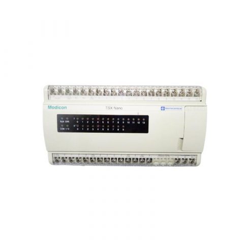
Schneider AEG AS-BDAU-208
1. Parameter Overview & Core Functions
The core function of the AS-BDAU-208 module is to provide analog signal output, with specific parameters as follows:Signal Type: Analog OutputNumber of Channels: 8 ChannelsOutput Range: ±10V (standard configuration); some specifications also support 0-10V or 4-20mA channel configurationsModule Form: Compact type, adopting TSX Compact rack mounting format, usually installed in cabinets at 2U or 4U heightCompatibility: A standard module of the Modicon AEG series PLC, suitable for the same series of CPU controllers (e.g., Q80 series)
2. Structure & Components
Digital-to-Analog Conversion (DAC) Circuit: Converts digital command signals from PLC into analog voltage signalsFiltering & Conditioning Circuit: Ensures the smoothness and accuracy of output signalsOutput Terminal Block: Provides terminals for easy wiring with field devices (e.g., frequency converters, speed regulators, proportional valves, etc.)Status Indicator Lights: Display the module’s operating status (e.g., running, fault, communication status, etc.)
3. Product Features
Precision Control: Offers a standard output range of ±10V, ideal for high-precision control requirements in industrial sitesCompact Design: As a member of the Compact series, it features a small size, suitable for use in control cabinets with limited spaceHigh Reliability: Schneider products typically have industrial-grade protection performance, adapting to harsh industrial environmentsModular Assembly: Facilitates flexible assembly and expansion according to the requirements of control systems
.jpg)
4. Application Fields
Process Control: Controls valve opening, pump flow or temperature set pointsMotion Control: Provides speed regulation signals for Variable Frequency Drives (VFD) to control motor speedInstrument Driving: Drives analog display instruments (e.g., voltmeters, ammeters)Process Automation: Used to adjust various process parameters on production lines in chemical, petroleum, metallurgy and other industries
5. Installation & Maintenance Recommendations
Wiring Notes:
- Input & Output Separation: To reduce electromagnetic interference, it is recommended to route input wires (signal collection) and output wires (signal transmission) separately, avoiding parallel or cross routing as much as possible
- Wiring Length: Input wiring should not be excessively long; it can be properly extended if the environment has low interference and small voltage drop. For output wiring, the impact of voltage drop on signal accuracy must also be considered
- Wiring Terminals: Normally Open (NO) contacts are preferred for wiring, which ensures consistency between ladder diagrams and actual wiring and facilitates troubleshooting
Troubleshooting: When output abnormalities occur (e.g., unstable voltage), check for voltage drop caused by high-current access or electromagnetic interference sources (e.g., motors, frequency converter switching power supplies) near the output wires
————————————————————————————————-
Main brand
ABB Allen-Bradley Alstom Bently Emerson Foxboro
GE MOOG Schneider Woodward HIMA Honeywel Triconex & more
Contact our professional team today for customized solutions to meet your electrical component needs.
📧 x13806028623@gmail.com / johnedward.zch@gmail.com
📞 +86 18250705533(Whatsapp)丨Sales Manager : Jinny/John


There are no reviews yet.